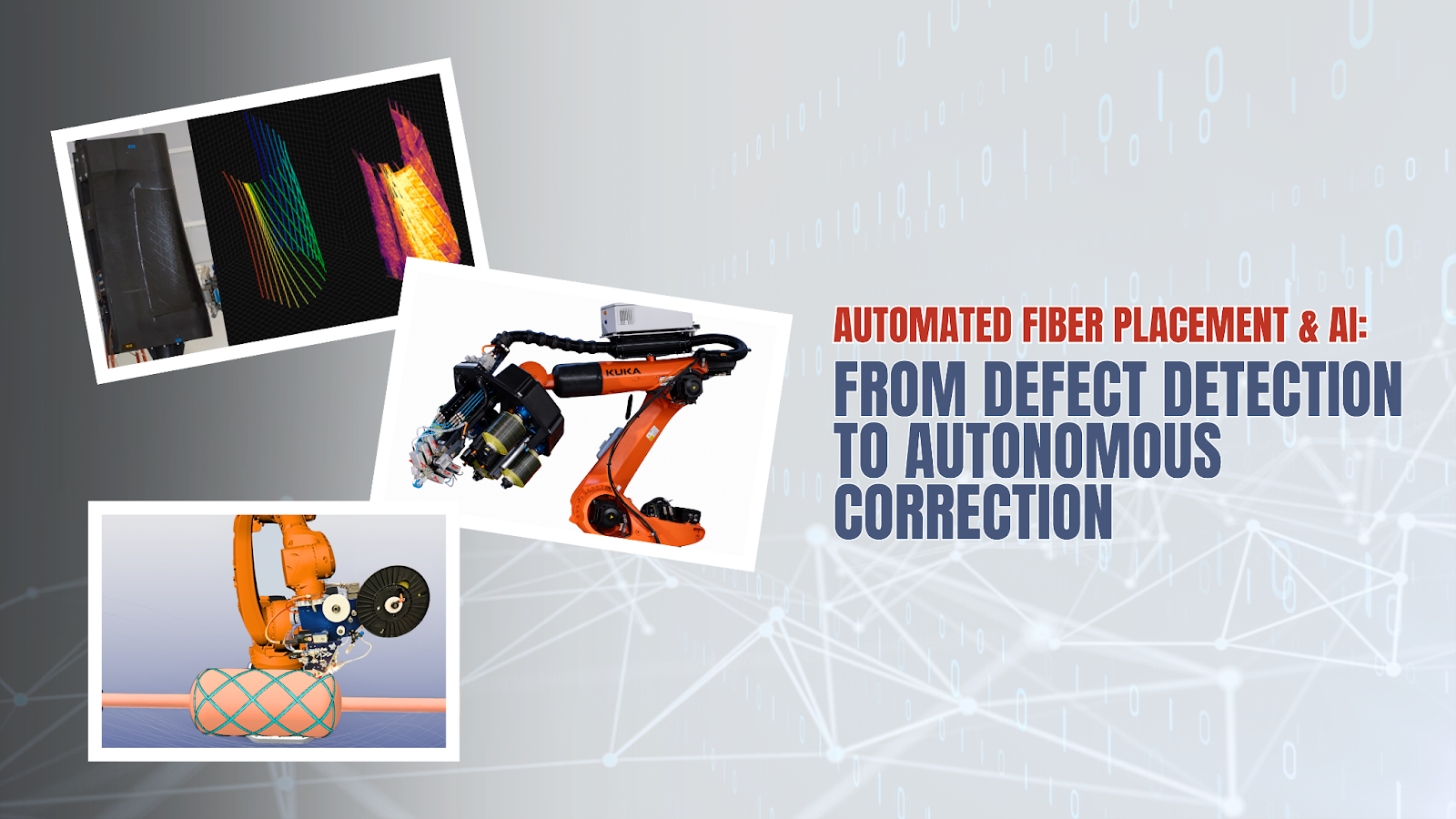
Sensor Fusion for In-Situ Defect Detection in Automated Fiber Placement: From Data Acquisition to Closed-Loop Control
A Technical Review of Real-Time Monitoring, AI-Driven Detection, and the Path to Autonomous Defect Correction
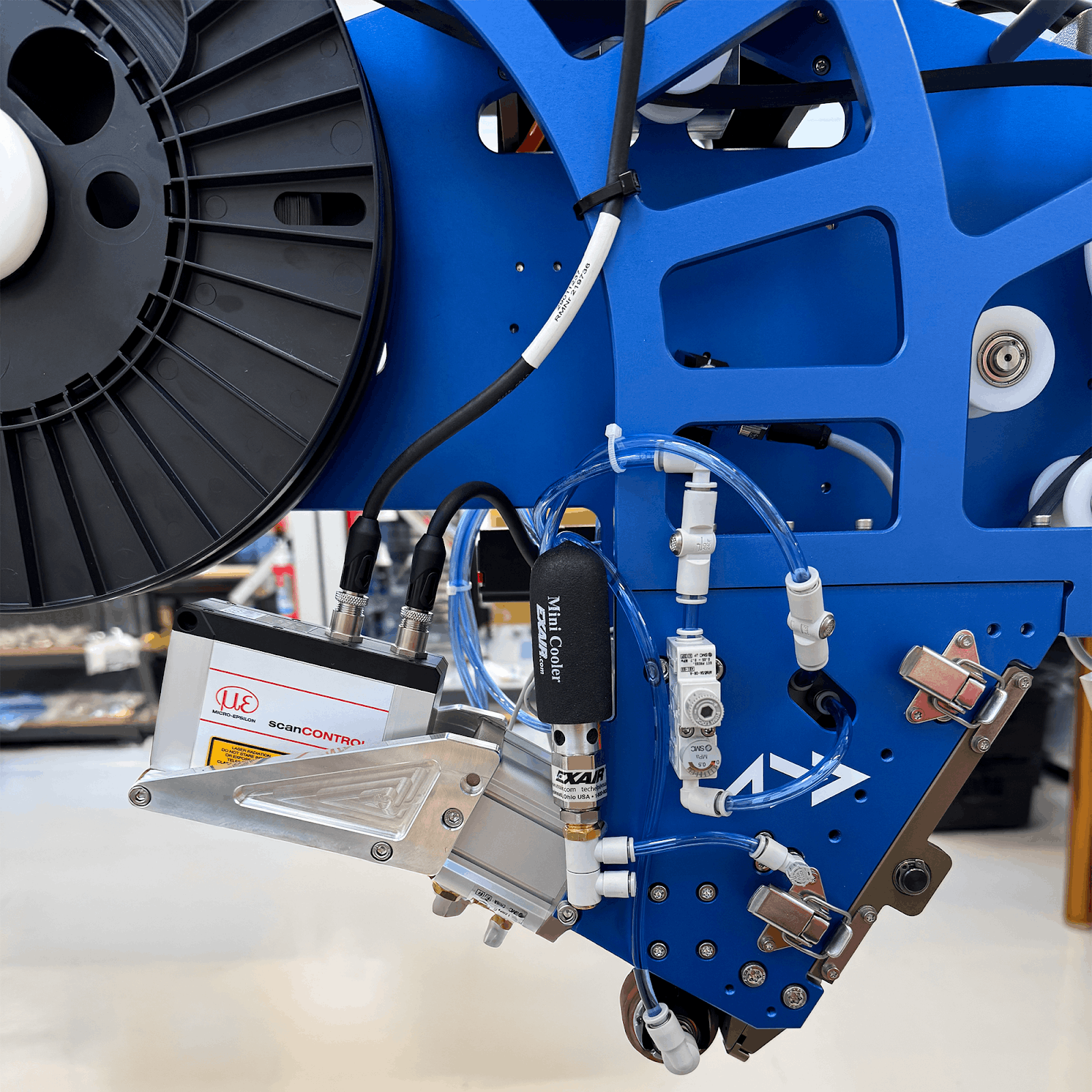
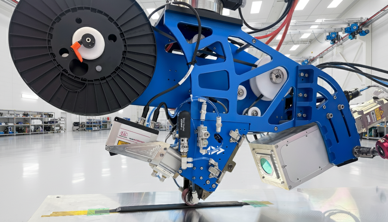
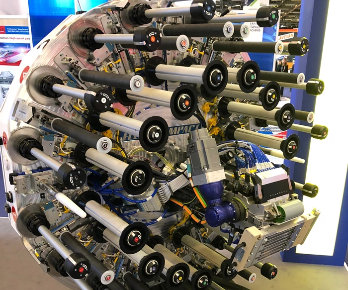
A modern AFP head integrates multiple sensor modalities for in-situ defect detection. The thermal camera (center) monitors heat distribution during layup, while a trailing laser profilometer measures surface topology. The compaction roller applies pressure to consolidate the deposited tow.
Introduction
Automated Fiber Placement (AFP) has become the dominant manufacturing method for large aerospace composite structures—accounting for approximately 50% of all aerospace composite construction. The technology enables precise, high-speed deposition of carbon fiber tapes onto complex geometries, producing fuselage sections, wing skins, and pressure vessels that would be impractical to fabricate manually.
But there's a problem: defects are inevitable.
Gaps between tows, overlapping material, twisted tapes, and bridging over contours—these manufacturing anomalies reduce mechanical performance by 7-32% and currently require extensive manual inspection and rework. The result is a process where the robot may be state-of-the-art, but quality control remains stubbornly human-dependent.
The industry is now at an inflection point. Sensors—thermal cameras, laser profilometers, and vision systems—are being integrated directly onto AFP heads, generating streams of data during deposition. Machine learning algorithms are achieving 94-99% accuracy in classifying defects from this data. The question is no longer "Can we detect defects?" but rather:
Can we detect, decide, and correct fast enough to keep the robot moving?
This review examines the state of sensor-based AFP monitoring from data acquisition through the largely unrealized goal of closed-loop defect correction. We identify a critical gap in the literature: while defect detection has advanced dramatically, automated correction—systems that stop the robot, remove defective material, and resume layup without human intervention—remains largely at the concept stage.
The Inspection Bottleneck
The Hidden Cost of Quality
Before discussing solutions, we must understand the scale of the problem. The data is stark:
| Metric | Value | Source |
|---|---|---|
| Inspection time as % of AFP cycle | 30-60% | Boeing/Fives |
| Rework + inspection time | 42% of cell time | NASA studies |
| Machine layup time | Only 19% of total time | Industry surveys |
| Manual inspection cost | ~50% of total cost of quality | Industry estimates |
| Defect rates without intervention | Up to 5.2% | Addcomposites data |
AFP Cell Time Distribution
How time is allocated in a typical AFP manufacturing cell
A typical AFP manufacturing cell spends more time inspecting and fixing defects than actually laying up material.
This inspection burden becomes even more critical as production rates increase. Next-generation aircraft programs demand cycle times that are incompatible with layer-by-layer manual inspection. The industry needs automated solutions that can inspect at production speed—or better, inspect and correct in real-time without stopping.
The Quality Variability Problem
Manual inspection introduces human factors:
Inspector fatigue during long builds (some parts require 100+ plies)
Subjectivity in defect classification
Inconsistent defect detection rates between inspectors
Time pressure leading to missed defects
Studies have shown that manual rework can sometimes make quality worse—shifting defect distributions rather than eliminating them. The case for automation is not just about speed; it's about consistency.
Taxonomy of AFP Defects
Defect Classification Framework
AFP defects can be systematically categorized based on their geometric characteristics and formation mechanisms:
AFP Defect Taxonomy
Systematic classification based on geometric characteristics and formation mechanisms
- Gaps Between tows or courses
- Overlaps Tow-on-tow or course-on-course
- Missing Tows Absent material in layup
- Position Errors Misaligned placement
- Wrinkles Fiber buckling
- Bridging Tow lifted from surface
- Twists Tow folds onto itself
- Puckers Localized out-of-plane
- Loose Tows Poor adhesion
- Twisted Tows Rope-like appearance
- Wandering Tows Deviating from path
- Splices Tow joints
- FOD Foreign object debris
Detailed Defect Characteristics
Gaps and Overlaps
Gaps occur when adjacent tows or courses do not meet, leaving an area of exposed substrate or previous ply. Overlaps occur when tows are deposited on top of each other, creating a local thickness increase.
.png)
.png)
In-Plane Defect Comparison
Gap vs Overlap — The two most common AFP manufacturing defects
| Characteristic | Gaps | Overlaps |
|---|---|---|
| Geometric signature | Two slight edges transverse to fiber | Three edges (gap + double thickness) |
| Height change | Negative (depression) | Positive (protrusion) |
| Typical width | 0.03" - 0.12" (0.76 - 3.0 mm) | 0.03" - 0.12" (0.76 - 3.0 mm) |
| Mechanical impact | 15-20% compression strength reduction | 15-20% compression strength reduction |
| Thermal signature | Distinct edges visible | Elevated temperature at overlap |
Root causes include layup strategy (rosette, natural, parallel path planning), tow spreading or wandering on compaction roller, tow width variation, robot positioning inaccuracy, and lateral tow movement (identified as the largest contributor).
Twists
A twist occurs when the tow folds transversely onto itself, creating a gap in surface coverage, doubled thickness over the folded region, and in extreme cases, "rope-like" rolled tow.
Twists show a characteristic topology: small altitude growth over their length, distinct from the sharper profile of wrinkles.
Bridging
Bridging initiates at the inside radius of a steered tow path, where the tow lifts from the tool surface—either partially or across the entire width—forming an arch of material not adhered to the substrate.
Detection challenge: Bridging can be subtle, with minimal height change but significant structural impact due to lack of adhesion.
Wrinkles
Fiber buckling creates out-of-plane undulations. Wrinkles are often caused by excessive steering curvature, inadequate compaction pressure, and tool geometry transitions.
Mechanical Impact Summary
| Defect Type | Strength Reduction | Critical Metric |
|---|---|---|
| Gaps (0.03-0.12") | 15-20% | Compression strength |
| Overlaps (0.03-0.12") | 15-20% | Compression strength |
| Single isolated defect | Up to 13% | Laminate performance |
| Multiple/clustered defects | Up to 32% | Structural integrity |
Sensor Technologies for In-Situ Monitoring
Overview of Sensing Approaches
Multiple sensor modalities have been explored for AFP monitoring. The table below summarizes the current landscape:
| Technology | Mounting | In-Situ Capable | Defect Types Detected | Maturity |
|---|---|---|---|---|
| Laser profilometry | AFP head | Yes (trailing) | Gaps, overlaps, twists, wrinkles | High |
| Thermal imaging | AFP head | Yes (in-process) | Gaps, overlaps, bridging, FOD | High |
| Structured light | External or head | Yes | Out-of-plane defects | Medium |
| Eddy current | AFP head | Yes (limited) | Fiber orientation, delamination | Medium |
| Ultrasonic | External | No (post-process) | Internal defects, voids | High (offline) |
| Machine vision (visible) | AFP head | Yes | Surface defects, tow edges | Medium-High |
Sensor Technology Comparison
Comparing AFP inspection sensor capabilities across key criteria
No single sensor excels across all criteria. Laser profilometry offers the best resolution but moderate gap detection; thermography provides the best real-time capability but lower resolution.
Laser Profilometry
Operating Principle: A laser line is projected onto the layup surface. A camera captures the reflected line, and triangulation calculates the 3D surface profile. Height variations indicate defects.
Specifications (Industrial Systems):
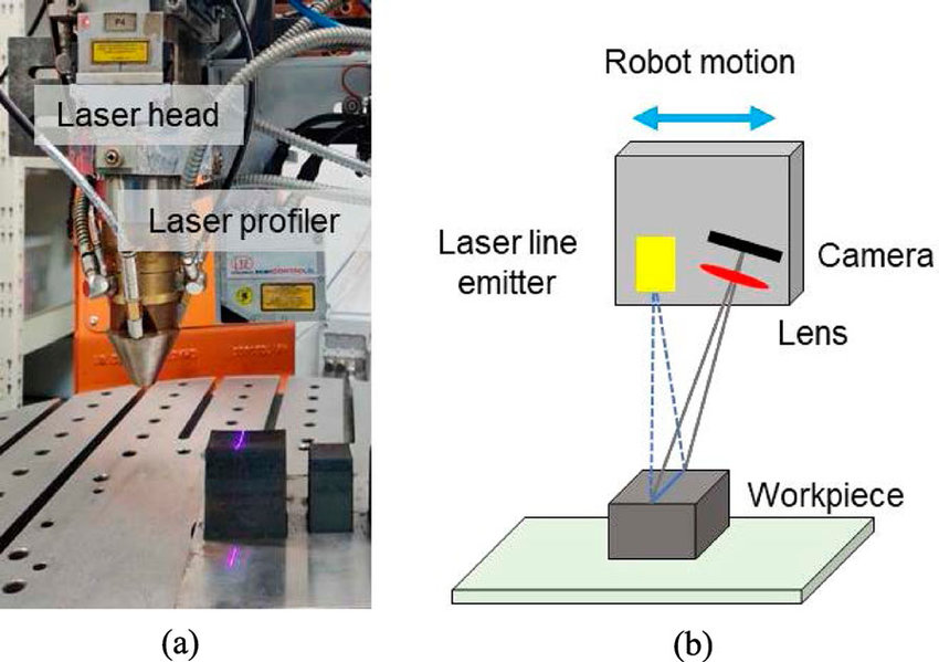
Image via ResearchGate – Surface defect identification in AM
Laser Profilometry Operating Principle
Laser triangulation technique for high-resolution surface inspection
Strengths:
- Mature, proven technology
- High precision for surface topology
- Robust detection of out-of-plane defects (twists, wrinkles, bridging)
- Quantitative height measurements
Limitations:
- Requires precise alignment to surface
- Limited sensitivity to in-plane defects (gaps/overlaps are "flat")
- Cannot detect internal defects (adhesion problems, voids)
- Historically used for off-process inspection; in-situ integration challenging
Recent Advances: The National Research Council of Canada and Fives developed an infrared interferometry-based profilometer that is angle-independent and more robust in ambient light conditions. This system mounts directly on the AFP head for true in-situ inspection.
AI-enhanced profilometry can now predict defects before they fully form. LSTM and CNN architectures trained on profilometry data have demonstrated the ability to forecast twist defects 5 mm before appearing under the sensor, and puckers 2 mm ahead, with 94% overall accuracy.
Thermal Imaging (Thermography)
Operating Principle: Infrared cameras detect thermal radiation emitted from the layup surface. The AFP heat source (hot gas torch, laser, infrared heater) creates thermal contrast that reveals defects as temperature anomalies.
Types:
- Passive thermography: Uses process heat (no external excitation)
- Active thermography: Additional heat source for enhanced contrast
.png)
The thermal image reveals gaps as dark lines (lower temperature, exposed substrate), overlaps as bright lines (higher temperature, double material), and tow edges as temperature gradients between tows.
Specifications (ISTIS - NASA's In Situ Thermographic Inspection System):
Strengths:
- True in-situ, real-time capability
- Non-contact, passive sensing
- Detects gaps, overlaps, twisted tows, bridging through thermal contrast
- Individual tow identification via temperature gradients
- Can identify beginning and end of tows
Limitations:
- Microbolometer sensors require 30+ minute warm-up for thermal stability
- Temperature drift compensation required
- Sensitive to ambient conditions
- Limited depth penetration (surface/near-surface only)
Defect Detection Mechanism:
| Defect | Thermal Signature |
|---|---|
| Gap | Distinct temperature edges at boundaries |
| Overlap | Elevated temperature (double material, different thermal mass) |
| Bridging | Abnormal cooling pattern (air gap beneath) |
| Twisted tow | Irregular thermal profile |
| FOD | Foreign thermal signature |
Eddy Current Testing
Operating Principle: An alternating electromagnetic field induces eddy currents in the electrically conductive carbon fibers. Defects alter the current flow patterns, which are detected by receiver coils.
Capabilities:
Unique Advantage: Eddy current can visualize fiber distribution and orientation non-contactly—detecting microscopic defects in dry carbon fiber or wet preforms including fiber misalignment, missing bundles, wrinkles, and gaps.
Structured Light / 3D Scanning
Operating Principle: Projected light patterns (stripes, grids) are deformed by surface topology. Cameras capture the deformation, and algorithms reconstruct 3D point clouds.
Recent Research (2025): PointNet++ neural networks trained on structured light point clouds can automatically segment out-of-plane defect regions including puckers, wrinkles, twists, bridging, and loose tows.
Sensor Technology Comparison Matrix
| Criterion | Laser Profilometry | Thermography | Eddy Current | Structured Light |
|---|---|---|---|---|
| In-situ capable | Yes (trailing) | Yes (real-time) | Yes (limited) | Yes |
| Gaps detection | Moderate | Good | Moderate | Moderate |
| Overlaps detection | Moderate | Good | Moderate | Moderate |
| Twist/wrinkle | Excellent | Good | Moderate | Excellent |
| Bridging | Good | Good | Poor | Good |
| Internal defects | Poor | Poor | Moderate | Poor |
| Resolution | ~3 µm | ~0.76 mm sizing | ~6 mm | ~10-50 µm |
| Processing speed | Fast | Fast | Moderate | Moderate |
| Maturity (AFP) | High | High | Medium | Medium |
Machine Learning and AI for Defect Detection
The AI Revolution in AFP Inspection
Traditional image processing struggles with the variability of defect appearance across different materials, layup conditions, and lighting. Machine learning—particularly deep learning—has transformed defect detection capabilities:
| Approach | Architecture | Accuracy | Application |
|---|---|---|---|
| CNN classification | ResNet | >99.4% | Defect type classification |
| SVM with thermal | Optimized SVM | 96.4% (F1: 96.43%) | Multi-class detection |
| Point cloud segmentation | PointNet++ | High | 3D out-of-plane defects |
| Anomaly detection | Autoencoder + LSTM | 94% | Predictive defect forecasting |
| Object detection | YOLO variants | Fast inference | Real-time localization |
CNN Architecture for AFP Defect Classification
Deep learning model for automated defect detection in thermal/profile images
Image
Convolutional Neural Networks (CNNs)
CNNs have become the dominant architecture for AFP defect image classification.
Training Data Challenges: Defective samples are rare in production (a good thing for quality, bad for ML training). Solutions include synthetic data generation (artificially created defect images), data augmentation (rotation, scaling, noise addition), and transfer learning (pre-trained networks fine-tuned on AFP data).
Key Finding: Adding 20% synthetic data to 200-300 real images per class can yield >99.4% detection accuracy with ResNet architectures.
Predictive Defect Detection
Perhaps the most significant recent advance is the ability to predict defects before they fully form.
Architecture: Autoencoder + LSTM + CNN pipeline processing laser profilometry data
Predictive Detection Pipeline
Deep learning architecture for ahead-of-time defect prediction
This predictive capability is crucial for closed-loop control—it provides the reaction time needed to adjust parameters or halt deposition before the defect is committed.
Unsupervised and Semi-Supervised Approaches
Labeled defect data is expensive to obtain. Recent work addresses this through unsupervised deep learning (learns normal patterns; flags anomalies), classical computer vision + DL hybrid (combines edge detection, thresholding with neural networks), and few-shot learning (effective classification with minimal labeled samples).
These approaches eliminate the need for large labeled datasets and defect samples, making them practical for production deployment.
Real-Time Considerations
| Architecture | Inference Speed | Suitable for Real-Time |
|---|---|---|
| ResNet-50 | ~20-50 ms/image | Yes (with GPU) |
| YOLO v9 | <10 ms/image | Yes |
| PointNet++ | ~100-200 ms/cloud | Marginal |
| LSTM ensemble | ~5-10 ms/sample | Yes |
Key Insight: Single-stage detectors (YOLO family) perform faster than two-stage methods (R-CNN family), making them preferred for real-time applications.
The Latency Challenge
Understanding the Time Budget
For closed-loop control, the system must complete the full perception-decision-action loop faster than the robot can deposit a defect-critical length of material.
Typical AFP Parameters:
Time Budget Calculation:
At 1 m/s layup speed with a 25 mm critical length:
Time to deposit defect: 25 ms
The entire sensor → processing → decision → robot command → actuation chain must complete in less than 25 ms to stop before the defect is committed.
Latency Breakdown
Latency Budget Waterfall Chart
Cumulative timing analysis for real-time AFP inspection at 1 m/s layup speed
| Stage | Typical Latency | Notes |
|---|---|---|
| Sensor acquisition | 1-10 ms | Camera frame rate dependent |
| Data transfer | 0.1-1 ms | EtherCAT: 30 µs for 1000 I/O |
| Image processing | 5-50 ms | GPU-dependent; YOLO ~10 ms |
| Decision logic | <1 ms | Simple threshold or rules |
| PLC/controller | 1-10 ms | Cycle time dependent |
| Robot command | 1-5 ms | Protocol dependent |
| Mechanical response | 10-50 ms | Inertia, actuator dynamics |
| Total | 20-130 ms | Highly variable |
Industrial Communication Protocols
Real-time robot control requires deterministic communication. Key protocols:
| Protocol | Cycle Time | Jitter | Application |
|---|---|---|---|
| EtherCAT | ≤100 µs | ≤1 µs | Motion control, sensors |
| PROFINET IRT | <1 ms | Low | Motion, drives |
| Ethernet/IP | ~2 ms | Moderate | General automation |
| Profibus (legacy) | ~10 ms | Higher | Older AFP systems |
Case Study: Early AFP systems using Profibus-connected PLCs had reaction times limited by the PLC cycle, constraining precision and throughput. Modern systems using EtherCAT achieve sub-millisecond deterministic control, enabling the tight timing needed for closed-loop operation.
Can AI Keep Up?
The honest answer: It depends.
For defect classification (identifying what type of defect after it's deposited), current AI systems are fast enough—10-50 ms inference times are acceptable for logging and alerting.
For defect prevention (stopping or correcting before the defect is committed), the system must be predictive. The 5 mm prediction horizon demonstrated with LSTM-CNN architectures translates to 5-25 ms of advance warning at typical layup speeds—marginal but potentially sufficient with optimized pipelines.
Critical Insight: The limiting factor is not usually AI inference time; it's the mechanical response time of the robot and end effector. Stopping a high-speed AFP head with significant momentum takes tens of milliseconds regardless of how fast the detection system responds.
From Detection to Correction: Closed-Loop Control
The Current State: Detection Without Correction
The majority of current AFP monitoring systems provide:
- In-situ detection — Identifies defects during layup
- Logging and visualization — Records defect locations and types
- Alerting — Notifies operators of detected defects
- Post-layup analysis — Statistical quality reports
What they generally do not provide is autonomous correction—the ability to stop, remove defective material, and resume layup without human intervention.
Why Closed-Loop Correction is Hard
| Challenge | Description |
|---|---|
| Mechanical complexity | Removing placed material requires cutting, lifting, and disposal—operations not in standard AFP heads |
| Material state | Thermoplastic prepreg may be partially consolidated; thermoset may have begun curing |
| Resumption accuracy | Restarting layup at the exact position with proper tension and adhesion |
| Decision uncertainty | Not all detected "defects" require correction; over-correction wastes time |
| Certification | Regulatory acceptance of autonomously corrected structures |
Levels of Closed-Loop Control
We propose a hierarchy of closed-loop capability:
Closed-Loop Control Maturity Levels
Evolution of AFP inspection and control capabilities
Open Loop (Baseline)
No in-situ monitoring. Manual inspection after layup. All corrections performed by humans.
Detect and Alert
In-situ sensors detect defects. System alerts operator. Human decides whether to stop. Human performs correction.
Detect and Halt
Automated defect detection. System autonomously pauses layup. Human assesses and performs correction. Human resumes operation.
Detect, Halt, and Assist
Automated detection and pause. System provides correction guidance. Human executes correction with system assistance. Semi-automated resume.
Adaptive Parameter Control
Continuous monitoring. Real-time adjustment of process parameters. Prevents defect formation through proactive control. No material removal required.
Full Autonomous Correction
Automated detection and halt. Autonomous defect removal. Autonomous repair/re-deposition. Autonomous resume and verification. No human intervention required.
Current Industry Status:
| Level | Status |
|---|---|
| Level 0-1 | Standard practice |
| Level 2 | Emerging in advanced cells |
| Level 3 | Research demonstrations |
| Level 4 | Active R&D focus |
| Level 5 | Concept stage only |
Adaptive Parameter Control (Level 4)
The most promising near-term path to closed-loop control is not defect correction but defect prevention through real-time parameter adjustment.
Controllable Parameters:
| Parameter | Effect on Defects | Response Time |
|---|---|---|
| Layup speed | Slower = better adhesion, fewer wrinkles | ~100 ms |
| Compaction pressure | Higher = better consolidation | ~50 ms |
| Heat input | Optimal temp = better tack | ~100-500 ms |
| Tow tension | Affects steering, bridging | ~50 ms |
| Path offset | Corrects gap/overlap accumulation | ~10 ms |
Research Example: The German Aerospace Center (DLR) demonstrated a gap control method using fiber edge detection sensors. The system determines relative positions of neighboring courses and corrects the actual path in real-time, maintaining gap tolerances without human intervention.

Industry Example:
Addcomposites' AddPath software creates a federated learning ecosystem where 50+ installed systems share process data. ML models trained on 12,000+ layup cycles have reduced defect rates from 5.2% to 0.8% through optimized parameters—without any automated material removal.
Toward Autonomous Rework (Level 5)
The full vision of closed-loop AFP includes autonomous rework capability. Required elements include defect localization (precise coordinates of defective region), material removal (cutting and extracting placed tow), surface preparation (ensuring substrate is ready for re-deposition), re-deposition (laying replacement material), and verification (confirming repair meets specifications).
Technical Approaches Under Development: Integrated cutting tools on AFP heads, vacuum extraction systems for removed material, local re-heating for thermoplastic re-bonding, and multi-pass strategies (detect on pass N, correct on pass N+1).
Current Limitation: No commercial AFP system offers fully autonomous rework. The literature on this topic is sparse, focusing primarily on feasibility studies and concept demonstrations rather than production-ready solutions.
Sensor Fusion Architectures
Why Single Sensors Are Not Enough
Each sensor technology has blind spots:
| Sensor | Cannot Detect |
|---|---|
| Laser profilometry | Internal defects, adhesion problems, subtle in-plane gaps |
| Thermography | Deep defects, precise dimensional measurements |
| Eddy current | Non-conductive materials, surface topology |
| Visible camera | Subsurface defects, transparent materials |
Sensor fusion combines multiple modalities to achieve comprehensive defect coverage.
Fusion Strategies
1. Data-Level Fusion
Raw sensor data combined before processing. Requires synchronized, aligned data streams. Highest information retention. Highest computational cost.
2. Feature-Level Fusion
Features extracted from each sensor independently. Features combined for classification. Moderate complexity. Robust to sensor noise.
3. Decision-Level Fusion
Each sensor produces independent defect decisions. Decisions combined (voting, weighted average, Bayesian). Simplest integration. May lose information.
Proposed Multi-Sensor Architecture for AFP
Multi-Sensor Fusion Architecture
Integrated data flow from sensors to decision-making for AFP inspection
Implementation Considerations
Synchronization:
- All sensors must be time-stamped to correlate with robot position
- EtherCAT provides <1 µs synchronization across devices
- Typical requirement: ±1 ms temporal alignment
Spatial Registration:
- Sensors have different fields of view and mounting positions
- Calibration matrices transform sensor data to common coordinate frame
- Robot kinematics provide real-time position reference
Data Rates:
| Sensor | Data Rate | Data Volume |
|---|---|---|
| Thermal camera | 30-60 Hz | 1-5 MB/s |
| Laser profiler | 1-32 kHz | 5-20 MB/s |
| Visible camera | 30-120 Hz | 10-50 MB/s |
| Eddy current | 100 Hz - 1 kHz | 0.1-1 MB/s |
| Combined | — | ~50-100 MB/s |
Edge vs. Cloud Processing:
- Edge (on-machine): Low latency, limited compute
- Cloud: Unlimited compute, network latency
- Hybrid: Edge for real-time decisions, cloud for analytics
Industrial Implementations
Electroimpact/Boeing: Integrated Multi-Sensor System
For Boeing 777X wing panel production, Electroimpact developed an automated in-situ inspection system integrating laser projectors (for operator guidance), high-resolution cameras (visual inspection), laser profilometers (surface topology), and custom software algorithms.
Result: Greatly reduced inspector burden and decreased overall run time while maintaining quality standards for large-scale production.
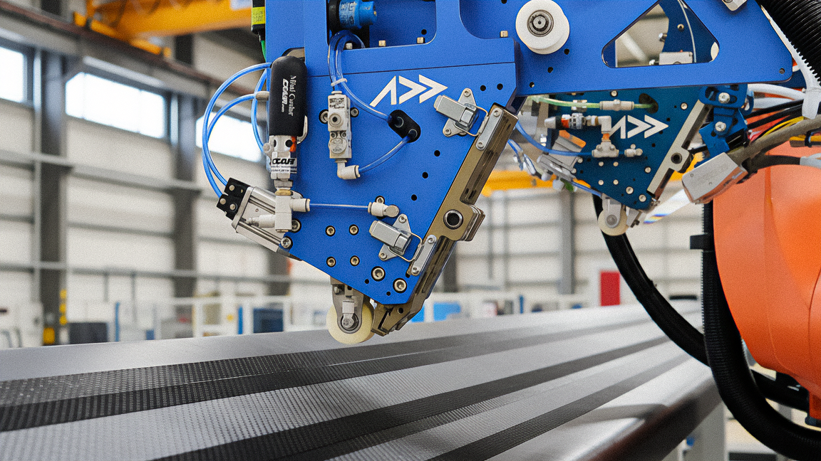
Automated fiber placement (AFP) head from Electroimpact. CW photo | Scott Francis
NASA ISTIS (In Situ Thermographic Inspection System)
Developed at NASA Langley Research Center for high-rate AFP manufacturing:
- Uses on-board heat source (no additional excitation needed)
- Detects all tested artificial manufacturing defects
- Sizes most defects to within 0.762 mm
- Minimal interference with layup operations
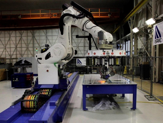
- Validated on ISAAC (Integrated Structural Assembly of Advanced Composites) system
Coriolis/Edixia Inline Inspection
French AFP manufacturer Coriolis and inspection specialist Edixia developed:
- Inline inspection detecting gaps, overlaps, twisted tows, fuzzballs
- 100% inspection during continuous production
- 20-30% productivity improvement vs. stop-and-inspect methods
Fives/NRC Advanced Profilometer
Fives and National Research Council of Canada developed:
- Infrared interferometry-based profilometer
- Angle-independent measurement
- Robust to ambient light
- Mounts directly on AFP head
- Accesses confined spaces better than conventional systems
Addcomposites: Federated Learning Ecosystem
Addcomposites' AddPath software represents a different approach:
- 50+ installed systems share anonymized process data
- ML models trained on 12,000+ layup cycles
- Defect rates reduced from 5.2% to 0.8%
- Closed-loop thermal control for thermoplastic processing
- 2025 partnership with Effman for turnkey manufacturing cells
The Literature Gap
Where Detection Ends and Correction Begins
Reviewing the academic and industrial literature reveals a clear pattern:
Literature Gap Visualization
Publication counts by research topic (2015-2025)
Abundant Research:
- Defect taxonomy and characterization
- Sensor technology development
- Machine learning classification algorithms
- Detection accuracy improvements
Sparse Research:
- Autonomous defect removal mechanisms
- Closed-loop path correction algorithms
- Re-deposition strategies after correction
- Certification frameworks for autonomously corrected parts
- System integration for full closed-loop operation
Quantifying the Gap
A 2024 survey on AFP defect rework noted that despite the 32-42% of cycle time spent on inspection and rework, there is "limited availability of information regarding the precise quality control outcomes obtained through manual rework."
A 2025 concept paper on adaptive path correction characterized the current state as lacking real-time control—"a core Industry 4.0 principle"—and presented only a proof-of-concept for in-process trajectory monitoring and control.
Why the Gap Exists
- Mechanical complexity: Adding rework capability to an AFP head requires significant hardware changes
- Risk aversion: Aerospace manufacturers are conservative; autonomous correction is uncharted territory
- Certification uncertainty: How do you certify a structure that was autonomously repaired?
- Economic calculation: For current production rates, human rework may still be cost-effective
- Research focus: Academic incentives favor novel detection methods over engineering integration
Opportunities for Future Research
| Research Area | Current State | Needed |
|---|---|---|
| Defect removal mechanisms | Conceptual | Prototype demonstration |
| Path re-planning algorithms | Offline optimization | Real-time re-planning |
| Re-deposition quality | Unknown | Characterization studies |
| Certification approach | Non-existent | Regulatory dialogue |
| Full system integration | Lab demos | Production-scale validation |
| Economic analysis | Assumptions | Data-driven ROI models |
Future Directions
Near-Term (2025-2027)
- Standardization of sensor interfaces for plug-and-play integration
- Real-time parameter adaptation achieving Level 4 closed-loop control
- Predictive defect AI with >5 mm advance warning becoming standard
- Digital twin integration for virtual validation of corrections
Medium-Term (2027-2030)
- First commercial autonomous pause-and-alert systems (Level 2-3)
- Regulatory frameworks for autonomously monitored structures
- Sensor fusion becoming standard (thermal + profile minimum)
- Federated learning networks spanning multiple OEMs
Long-Term Vision (2030+)
- Full autonomous rework capability (Level 5) for select defect types
- Zero-defect AFP through predictive prevention
- Certification credit for in-situ inspected structures (reduced post-cure NDI)
- Self-optimizing AFP cells that continuously improve through operation
Conclusions
Summary of Key Findings
The inspection bottleneck is real and significant. AFP cells spend 30-60% of their time on inspection and rework—more than on actual layup. This is unsustainable as production rates increase.
Detection technology has matured. Laser profilometry and thermography, enhanced by deep learning, achieve 94-99% defect detection accuracy. The sensors exist; they are being integrated onto AFP heads.
AI can be fast enough—barely. With YOLO-class detectors achieving <10 ms inference and predictive algorithms providing 5+ mm advance warning, the AI is not the bottleneck. Mechanical response time is.
Closed-loop correction remains elusive. The literature is rich on detection but sparse on correction. No commercial system offers fully autonomous defect removal and repair.
Adaptive parameter control is the near-term path. Rather than detecting and removing defects, preventing them through real-time parameter adjustment is more achievable and is showing production results (5.2% → 0.8% defect rates).
Sensor fusion is necessary but under-developed. Single sensors have blind spots; multi-sensor systems are demonstrated in research but not yet standard in production.
Recommendations
For Researchers:
- Focus on the correction side of the loop, not just detection
- Develop and publish defect removal mechanisms
- Characterize re-deposition quality after autonomous repair
- Engage with certification bodies early
For Industry:
- Invest in Level 4 (adaptive parameter control) as the practical near-term goal
- Standardize sensor interfaces to enable sensor fusion
- Collect and share (anonymized) defect data to improve ML models
- Begin dialogue with regulators on certification credit for in-situ inspection
For Regulators:
- Develop frameworks for autonomously monitored structures
- Consider certification credit for verified in-situ inspection
- Engage with industry on practical requirements for autonomous correction
The Path Forward

The vision of fully autonomous AFP—where the robot detects a defect, pauses, removes the bad material, re-deposits, verifies, and continues without human intervention—is technically achievable but not yet realized. The components exist: fast sensors, accurate AI, real-time robot control. What's missing is the integration, the certification framework, and the will to cross the gap from detection to correction.
The industry that solves this problem first will set the standard for next-generation aerospace composite manufacturing.
References
[1] Oromiehie, E., Prusty, B.G., et al. (2019). Automated fibre placement based composite structures: Review on the defects, impacts and inspections. Composite Structures, 224, 110987.
[2] Croft, K., Lessard, L., et al. (2011). Experimental study of the effect of automated fiber placement induced defects on performance of composite laminates. Composites Part A, 42(5), 484-491.
[3] Schmitt, R., et al. (2007). Machine vision system for inspecting flaws in textile semi-finished products for wind rotor blades. Optical Engineering, 46(5).
[4] Denkena, B., et al. (2016). Thermographic online monitoring system for Automated Fiber Placement processes. Composites Part B, 97, 239-243.
[5] Zambal, S., et al. (2019). Accurate fibre orientation measurement for carbon fibre surfaces. Pattern Recognition, 88, 75-87.
[6] Cemenska, J., et al. (2014). Automated In-Process Inspection System for AFP Machines. SAE Technical Paper 2015-01-2608.
[7] Gregory, E., et al. (2021). In Situ Thermal Inspection of Automated Fiber Placement for manufacturing induced defects. Composites Part B, 220, 109002.
[8] Harik, R., et al. (2018). Automated fiber placement defects: Automated inspection and characterization. SAMPE Conference Proceedings. NASA/CR-2018-220118
[9] Sacco, C., et al. (2020). Machine learning in composites manufacturing: A case study of automated fiber placement inspection. Composite Structures, 250, 112514.
[10] Tang, Y., et al. (2025). Lay-up defects inspection for automated fiber placement with structural light scanning and deep learning. Polymer Composites.
[11] Böckl, B., et al. (2023). Effects of defects in automated fiber placement laminates and its correlation to automated optical inspection results. Journal of Reinforced Plastics and Composites, 42(11-12).
[12] Pantoji, S., et al. (2024). Predicting gaps and overlaps in automated fiber placement composites by measuring sources of manufacturing process variations. Composites Part B, 283, 111683.
[13] Krombholz, C., et al. (2023). Automatic process control of an automated fibre placement machine. Composites Part A, 167, 107420.
[14] Lukaszewicz, D., et al. (2012). The engineering aspects of automated prepreg layup: History, present and future. Composites Part B, 43(3), 997-1009.
[15] Composites Knowledge Network (2024). Automated fibre placement (AFP) - A303. CKN Knowledge in Practice Centre.
[16] CompositesWorld (2023). Automated, in-situ inspection a necessity for next-gen aerospace.
[17] NASA (2023). Composites From in-Situ Consolidation Automated Fiber Placement of Thermoplastics for High-Rate Aircraft Manufacturing. NASA Technical Reports.
[18] Addcomposites (2024-2025). Technical documentation: AFP-XS System, AddPath Software.
[19] Fereidouni, M., Van Hoa, S. (2025). In-situ consolidation of thermoplastic composites by automated fiber placement: Characterization of defects. Journal of Reinforced Plastics and Composites.
[20] IEEE (2025). Future-Proof Adaptive Path Correction in Automated Fibre Placement: A Concept Demonstration. IEEE Conference Proceedings.
[21] ResearchGate (2017). Architecture for accelerating processing and execution of control commands in ultrafast fiber placement robot. International Journal of Robotics and Control.
[22] Fives/NRC (2020-2024). In-Process Inspection (IPI) technology development reports.
[23] Electroimpact (2019). Automated fiber placement inspection system for Boeing 777X. SAE Technical Paper.
[24] Coriolis/Edixia (2023). Inline inspection for AFP. CompositesWorld.
[25] MDPI Polymers (2020). Defect Characteristics and Online Detection Techniques During Manufacturing of FRPs Using Automated Fiber Placement: A Review.
[26] Frontiers in Manufacturing Technology (2024). Anomaly detection in automated fibre placement: learning with data limitations.
[27] NASA Technical Reports (2017). Advances in In-Situ Inspection of Automated Fiber Placement Systems.
Learn More
Have questions about implementing sensor fusion for your AFP operations?
Contact Us for a Consultation